Customer service:
400 069 8158

I. Overview
With the rapid development of Internet technology and information communication technology, the wave of informatization and intelligence is sweeping every corner of the world . The rise of intelligent and digital homes has adapted to social informatization and economic internationalization. Intelligent building communities have become the leading direction of real estate investment and development. Due to the continuous improvement of people's living standards , more and more attention is paid to the quality, safety and information acquisition and management of residential quarters, which has greatly promoted the development of intelligent digital homes .
The irreplaceable role played by intelligent communities in community property management and the application of smart homes in construction, decoration and life have become an unstoppable historical trend! This trend gave birth to the rapid development of the digital community system.
At present, most of the domestic smart communities are mainly based on simulation technology. Although many smart subsystems are also configured, due to the limitations of simulation technology, there is no good integration between the subsystems, and the application of the subsystem itself is also There are big shortcomings, and the intelligent system inside the home is limited to very basic functions . Digital cell system is in digital technology, broadband network as the core, highly integrated community intelligence platform as a carrier, the family unit , subject to the overall community to achieve a modern residential area a variety of digital applications . " Digital technology community " in the existing " intelligence community " based on the full import of digital technology and information technology to dramatically improve the intelligence level of the cell, the real digital life of the family. Digital technologycomprise cell security, Internet applications and property management automation applications . In the digital cell system, when performing functional design, technical route selection, and equipment configuration, the functional requirements must be determined by market positioning, and follow the principle of"technology and function matching, equipment and technology matching, equipment and equipment matching", from economy and reliability Comprehensive evaluation of products in terms of nature, openness, scalability and sustainability, abandoning concepts and hype, focusing on practicality, allowing owners to truly experience the “digital and networked” lifestyle of the times, and also for property management The department feels a very real "integrated and automated " management method.
2. The development history of the building intercom system
China building intercom industry to the present, from the time roughly experienced the following three stages:
1. The first stage of the development of building intercom: (4+N type)
Early building intercom system products have a single function. The system only uses code-sending and decoding circuits or RS-458 to communicate in a single building in a small area, which cannot achieve large-area networking in the entire community. This kind of decentralized control system is incompatible with each other and is independent of each other. It mainly implements simple single-user and unit-type building intercom products, which is not conducive to the unified management of the community.
2, building intercom development of two phases: bus
With the development of technology and the improvement of the living standards of the Chinese people, the demand for them is gradually increasing. The original non-networking and non-visual requirements can no longer meet the needs of people, so it enters the networking stage. After 1998, networking has become the most basic requirement for intelligent buildings. The control network technology of the community widely adopts the field bus technology of single-chip microcomputer technology. Such as CAN, BACNET, LONWORKS and domestic AJB-BUS, WE-BUS and some buses realized by RS-485 technology. The use of fieldbus technology can interconnect, network, manage, and coordinate the various scattered systems in the community, thereby forming a relatively large regional system. The application of fieldbus technology in the community has made the intercom system a big step forward. Building intercom products have entered the second stage of rapid development, and large-scale community networking and comprehensive intelligent building intercom equipment have begun to emerge. However, from the perspective of the demand market, the product has entered the demand platform area. After a large number of applications, the traditional bus video intercom system also shows certain limitations:
(1) Single function, most products are limited to functions such as calling and unlocking, and the equipment utilization rate is low;
(2) The anti-interference ability is poor, and the sound or image is often disturbed and unclear;
(3) The transmission distance is limited, and a video amplifier needs to be added when the distance is long. It is difficult to connect to the network when the community is large, and the cost is high;
(4) Due to technical limitations, product upgrades or expansion of functions are difficult.
To 2000, the introduction of network video intercom systems, digital control signal using cable transmission, coaxial cable transmission of audio and video intercom systems, requiring two wire gauge. This system breaks the traditional bus structure and provides a feasibility testimony for the transition of the building intercom system to the digital stage. Therefore, it belongs to the 2.5 generation product.
3, building intercom development of three phases: TCP / IP networking type
With the popularization of Internet applications and the narrative development of computer technology, people's work and life have undergone great changes. The concept of digital and intelligent communities has been accepted by more and more people, and building intercom products have entered the third In the stage of rapid development, multi-functional intercom equipment began to emerge. Local area network technology development products based on ARM or DSP technology are gradually launched, and digital intercom technology has a breakthrough development! Using the network to transmit data obscures the concept of distance and breaks through the traditional concept. Integrate the security system into the equipment to improve the practicability of the equipment.
(1) Suitable for complex, large-scale and ultra-large-scale community networking requirements;
(2) The digital indoor unit realizes the transmission of digital, voice, and image through a network cable, which eliminates the need for data bus, audio cable and video cable. Just connect the digital indoor phone to the indoor information point;
(3) It can realize multi-channel intercommunication at the same time, without the phenomenon of busy;
(4) It has a great impact on the mid-to-high-end market of the industry and can develop across industries;
(5) The cost of setting up a network is low, which is easy to upgrade and expand;
(6) Easy maintenance and product upgrades.
3. System design basis
The video intercom system of Shenzhen Zhensheng Intelligent Electronics Co., Ltd. is designed based on the national intelligent community design standards and is an intelligent product developed by network, information, and digital technology. It has a high level of digitalization, good compatibility, and high system integration. , The design basis is:
"Intelligent Building Design Standard" ( GB/T 50314-2000);
"Code for Electrical Design of Civil Buildings" ( JGJ/T 16-92);
"The People's Republic of China Security Industry Standards" ( GN/T74-94);
"People's Republic of China Public Safety Industry Standard" ( GN/T70-94);
"Code for Design of Building Electrical Appliances" ( IGI16-33);
"Household Telecommunications Wiring Standard" ( ANSI TIA/EIA-570A)
"Digital Application of Property Management in Construction and Residential Community"
"Application of Digital Technology in Construction and Residential Community Operation Services"
"Test and Acceptance of Digital Technology Application System for Building and Residential Communities"
"Code for Design of Integrated Wiring System Engineering for Buildings and Building Groups" ( CECS72-95)
"Commercial Building Communication Wiring Standard" ( ANSI/EIA/TIA-568A)
"The Original User Building Wiring" ( ISQ/IEC IS-11801)
"Commercial Building Communication Path and Space Structure Standard" ( ANSI/EIA/TIA-569)
Shenzhen Zhensheng Intelligent Electronics Co., Ltd. The solution of the video intercom system: full digital transmission, full digital control, and digital integration; the design follows the "six modernization" design ideas, which are: product digitalization, protocol standardization, and function integration Design ideas of modernization, application fashion, service specialization, and price-friendly design.
l Product digitalization: adopt advanced digital technology in product system design.
l Protocol standardization: adopt standard TCP/IP protocol network technology in system transmission ,
l Function integration: Comprehensive and diverse in function, with many expansion and value-added functions.
l Application fashion: The product appearance is designed for fashionable household products. The fashion not only shows in appearance, but also pursues fashion in application, providing people with fashionable applications that keep pace with the times, such as electronic photo albums, convenient information, etc.
l Service specialization: Provide professional all-round services, tailor-made solutions for you.
l The price is close to the people: Shenzhen Zhensheng Intelligent Electronics Co., Ltd. provides people with high-end products. In terms of prices,we are looking for prices that are close to the people. Only in this way can we truly serve millions of households.
Five, system topology


![]()
![]()

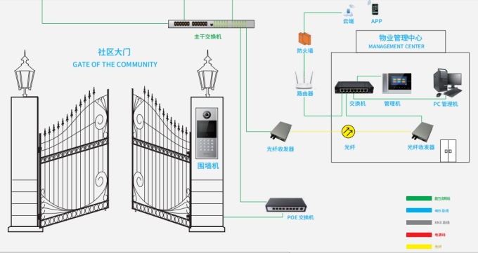
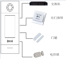
systems mannual:
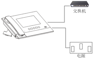
1. The basic components of the community can be divided into buildings and villa groups;
2. The community usually sets up one management center, and large communities can set up multiple management centers according to the actual situation, which is convenient for the property to provide services and improve work efficiency;
3. In network construction, terminal connections use PoE switches for network connections and equipment, and intermediate and central network switches use Layer 2 network switches for connection;
4. In the transmission process, the short distance is used for the connection of the super five-type line, and the long-distance transmission is used for the connection of the optical fiber;
5. Set up one or more wall machines in the community according to the actual situation;
6. According to the needs of residents in the community, KNX smart home services and security alarm functions can be extended for the residents .

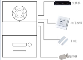
1. The unit building is the basic part of the community and the main part of the digital building intercom system.
2. A digital intercom host is installed at the door of the unit, which is used to realize the call visual intercom and door unlocking functions of the owners and visitors. If there is an underground parking lot, a digital intercom host can be set up according to the on-site situation, which is convenient for the owners and visitors. Access management.
3. The network architecture inside the building needs to be designed and configured according to the actual situation according to the height of the building and the number of households on each floor.
4. CAT-5 transmission is used inside the building to form the internal network architecture of the building.
5, the indoor unit, single-family door machine, door machine using PoE power supply power, the choice of PoE switches shall earthquake intelligent sound ofPoE switches.
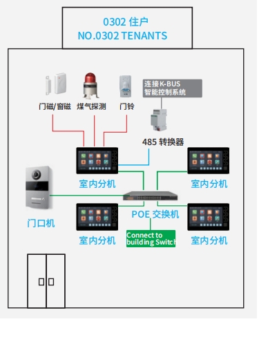
1. Indoor network architecture is the core unit of building intercom. It is the ultimate experience place for system digitization.
2. Install one to four indoor extensions inside the households, which can realize all the functions of building intercom, and is the center of home security and intelligent control.
3. Through this indoor extension, the system can expand the security monitoring of 8 defense zones;
4. According to customer needs, provide customers with optional video surveillance functions;
5. Through the configuration with the indoor unit, it can provide users with services such as call transfer.
6. According to the customer's home meter and other intelligence level, the system can also provide users with direct automatic intelligent meter implementation and detection services, so as to further improve the management level of the community property.
Seven, system function introduction
1. Visual intercom function
It can realize the visual intercom between the entrance and exit of the community and the residents, the stairs and the residents, and the management center and the residents, and the voice and image are clear.
2. Unlock function
During a call, the indoor unit can unlock the calling door phone or wall phone, the management unit can also unlock the calling wall phone or door phone, and the residents can also unlock by swiping their cards or passwords.
3. Monitoring function
The indoor unit can monitor the door phone in real time, or the network camera in the community, and the management unit can also monitor the door phone wall unit, and supports switching between different door phones during monitoring.
4. Multi-channel function
The system uses TCP/IP networking. On the same backbone 100M LAN network, devices with sufficient bandwidth of 100 channels can perform audio and video intercom at the same time, so that different calls are not busy at the same time.
5. Household calls
The indoor units of different households in the two communities can call each other.
6. SOS emergency call
There is an SOS emergency soft key on the indoor unit. By pressing this key, the management unit can receive the alarm information of the alarm indoor unit and display the indoor computer room number.
7. Defense zone alarm
It has 8- channel defense zone alarm function, and can support expansion to 24- channel defense zone. When armed, it will automatically report to the management center when it encounters an alarm.
8. Graphical information publishing and receiving function
The upper computer of the management center (need to install the supporting system management software) can send text messages to the indoor unit and door phone (the indoor unit can be attached with pictures).
9. Online access control function
It can realize the online network access control function through the intercom system equipment.
10 , an image storage function
The indoor unit has the function of capturing and storing the visitor images of the door phone or wall unit.
11 , tamper alarm
Indoor units, VTOs, and single-family VTOs have built-in anti-dismantling devices. When they are disassembled, they will give an alarm and upload them to the management center.
8. Selection of main equipment of the system
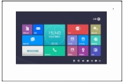
NH-SF07-2
| NH-SF07-2 | |
This product is a device based on the TCP/IP transmission protocol and is the main component of the digital building intercom system. It supports visual intercom, defense zone settings and standby picture push display. | ||
Features Designed with 7 -inch capacitive touch screen; Support 24V non-standard PoE power supply; Support to connect doorbell and single door phone; The call function can be expanded to accept the call from residents / visitors; Support real-time monitoring, can monitor door phone, IP camera; Receiving and sending information, and can exchange information with the management center; Support one household with multiple extensions, withdraw / arm and mute synchronization function; It can realize the visual intercom between visitors and residents, residents and management center; It has the functions of indoor and household intercom, which can realize the intercom between residents in the community; It has a standard 7- zone security alarm function.
| ||
Working voltage: DC 24V Working current: ≤ 150mA Quiescent current: ≤ 80mA Ringing time: 30 seconds Talk time: 120 seconds Monitoring time: 30 seconds Ambient temperature: -10 ℃ ~ + 55 ℃ Product dimensions ( W is / H / D ) : 22 0 *. 1 . 4 0 *. 1 . 7 . . 5 mm | Display screen: Type: LCD Size: 7 " Resolution: 1024 * 600 | |
NH-SF07-2
Instructions
| |||||||
Setting instructions | |||||||
1. System Settings | Project settings | ||||||
1. Time setting | 2. Camera settings | 3. Call forwarding settings | 1. Room number setting | ||||
4. Password setting | 5. Alarm setting | 6 single-family door phone settings | 2. Restore factory settings | ||||
7. Ringtone settings | 8. Access control settings | 9. Display settings | 3. Setting of small door phone 1 | ||||
10. Language setting | 11. About | 12. Project settings | 4. Small door phone 2settings | ||||
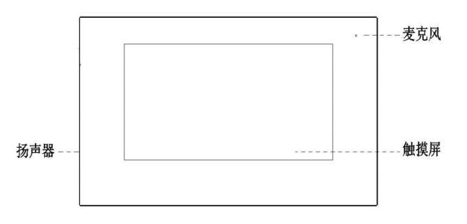
Interface Description
| Interface diagram
|
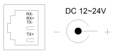
Number ①: +12V + GND : voltage output. Z8 : Zone interface, only supports normally open security module interface. Z7 to Z1 : Standard zone interface, supports access to normally open / normally closed security modules. Number ②: Network interface (support non-standard PoE power supply). No. ③: power input the DC 12 is V 24 ~ V . | |
Z(1~7) Single security detector connection method:
|
| Z8 single defense zone connection method:
| |
Z(1~7) Connection of multiple security detectors :
|
| ||
The connection method of Z8 multiple security detectors:
| |||

Trigger type
Immediate alarm: After the defense zone is armed, an alarm will be issued immediately once it is triggered.
Delay alarm: If the zone is triggered after arming, it will enter the alarm delay countdown, and the user can disarm within the countdown time, otherwise the alarm will be issued immediately after the time is up.
Transmission delay: This zone needs to be associated with the delay zone. After arming, once the defense zone is triggered before the delay zone, it will alarm immediately; if the delay zone is triggered first, the trigger countdown will be executed, and the user can disarm within the countdown time, otherwise the alarm will be immediately triggered when the time is up.
Report within 24 hours: The zone will be detected as long as the system is powered on, and will not be affected by arming / disarming. Once the zone is triggered, an alarm will be issued immediately.
Cross alarm: This defense zone needs two defense zones to cooperate and trigger. After arming, once the cross zone is triggered, if the cross zone 2 is triggered within 5 seconds, an alarm will be issued immediately, otherwise no alarm will be issued.
The doorbell function can be set through the alarm  Defense zone settings
  The detector type is set. After the setting is completed, the zone interface detects the doorbell input and immediately rings the doorbell.
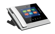
NH-SG10 | NH-SG10 | |
This product is a device based on the TCP/IP transmission protocol, and is a central device that manages the residents of the community and the host at the entrance and exit. | ||
Features Designed with 7 -inch capacitive touch screen; Can receive calls from indoor station and door station Synchronously respond to the alarm signal of the indoor unit; With alarm information storage function; With remote unlocking function, it can unlock the door phone / wall phone; Can display indoor / door phone number; Can monitor door phones, wall cameras, and network cameras; Support emergency unlocking (the unlocking time is 1 hour). | ||
Working voltage: DC 24V Working current: ≤ 200mA Quiescent current: ≤ 80 Ma Ringing time: 30 seconds Talk time: 120 seconds Monitoring time: 30 seconds Ambient temperature: -10 ℃ ~ + 55 ℃ Dimensions (L * W * D without base and handle ) : 305 * 210 * 31.8 mm | Display : Type: LCD Size: 7 " Resolution: 800 * 480 | |
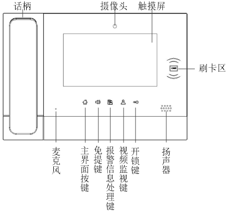
Front view of management machine
Instructions
| ||||
Setting instructions | |||
System settings | Project settings | ||
1. Time setting | 2. Language setting | 3. Password setting | 1. Number setting |
4. Display settings | 5. Ringtone settings | 6. Project settings | 2. Restore factory settings |
7. About | 8. Inbound management | ||
Interface Description
| Interface diagram
|
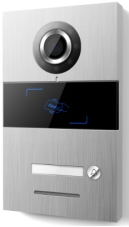
Door phone
NH-SACR07-01 | NH-SACR07-01 | |||
This product is the main component of the digital building intercom system. It adopts standard five-category line connection, so as to realize the conversation with the indoor unit or the management unit, and supports IC card access control. | ||||
7 inch TFT display Support IC card swiping High-bright LED lights at nightautomatically fill light Door status detection, door open overtime alarm Provide normally open / normally closed lock | extensions: Support face recognition to unlock Random password and QR code unlock (Need to be used with the cloud intercom APP , the factory default does not support) | |||
Working voltage: DC 24V Working current: ≤ 300 mA Quiescent current: ≤ 1 5 0mA Ambient temperature: -25 ℃ ~ +70℃ ( W/H/D ) 148.5 * 363 * 47 mm
| Display : Type: LCD Size: 7 " Resolution:60 0 × 1024 | Camera : Type: CMOS Pixel: 20 0W Viewing angle: Diagonal 1 23 ° Focal length: 3 .5mm Fill light method: white light Minimum illumination:0 lux | ||
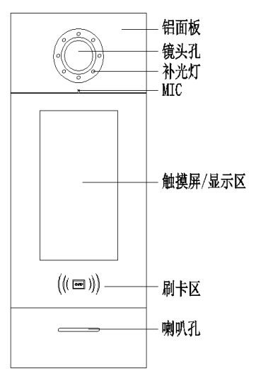
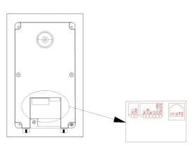
Front view of door phone
Interface Description
| Interface diagram
| ||||
Number ①: Network interface (support standard PoE power supply, need to be customized). No. ②: power input the DC 24 V . Number ③: +12V : +12V voltage can only be provided when the VTO input voltage is >18V .When using +12V input voltage, this output will be lower than +10V . COM NO NC : Common terminal, normally open terminal and normally closed terminal of the unlocking relay. GS : Door status detection input terminal. UNLOCK GND : Door unlock switch input | |||||
Instructions
| |||||
Setting instructions | |||
2. System Settings | 3. Project settings | ||
1. Time setting | 2. Sound settings | 1. Equipment attributes | 2. Alarm setting |
3. Language setting | 4. Password setting | 3. Alarm setting | 4. Factory settings |
5. Unlock settings | 6. Access card settings | 5. Engineering password | 6. Company information |
7. Elevator linkage | 7. Equipment information | ||
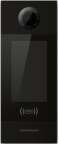
Single household door phone
NH-SAA-01 | NH-SAA-01 | ||
This product is a single door phone of the H series digital building intercom system. It adopts standard five-category line connection, so as to realize the video intercom call with the room machine or the management machine, and supports IC access control. | |||
Features Support swiping IC card Support calling indoor unit, management unit Adjustable unlocking time Door status detection, door open overtime alarm Provide normally open /normally closed unlock output Support online upgrade | |||
Working parameters Working voltage: DC 24V Quiescent current: ≤ 60mA Working current: ≤ 130mA Working environment temperature: -25 ℃ ~70 ℃ Storage environment temperature: -40 ℃ ~70 ℃ Product size (W/H/D): 120×194 × 44.7 mm | Camera Type: CMOS Pixel: 30W Viewing angle: 110 ° diagonal Minimum illumination: 0 lux Focal length: 2.2mm Fill light method: white light | ||
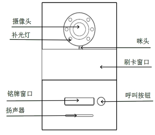
Front view of small door phone
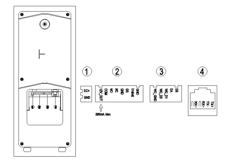
Interface Description
| Interface diagram
| ||||||||
RJ45 network interface: connection line interface, which can be connected to 24V non-standard PoE switch; NO COM NC : Normally open / normally closed interface; GS GS-GND : Door status detection interface; UNLOCK : unlocking interface inside the door; GND DC+ : Independent power supply interface; | |||||||||
Configuration
| |||||||||
The visitor short presses the call button to start the call, and the machine rings a ring back tone. If you short press the call button during ringing, the 30- second countdown will be reset . If you press and hold the call button during ringing, switch to the call management center. If theresident does not answer within 30 seconds, the call will be ended automatically | The visitor presses the call button for 2seconds to start the call, and the machine rings a ring back tone. If the management center does not answer within 30 seconds, the call is automatically ended. If you press and hold the call button while ringing, the30- second countdown will be reset , and if you press it shortly, it will switch to the household.
|
1. Swipe to unlock Place the registered card close to the card swiping area on the single-family door machine to unlock it. 2. Unlock the indoor unit When calling a resident or the resident is monitoring a single-household door phone, the indoor station can control the unlocking of the single-house door phone. 3. Unlock the door button This machine provides an interface for wiring the exit button. After the exit button is connected, the residents only need to press the exit button inside the door to unlock. | |
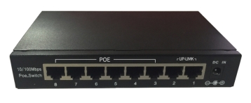
( PoE 6+2 ) switch is a non-standard Layer 2 network switch with POE power output. All ports support Auto MDI/MDIX function, providing a simple, economical, high-performance standard network solution , It is simple and flexible, easy to install, superior in performance, and cost-effective. It is an ideal choice for you to increase the speed of service. The product 1~8 ports are 24V forced power supply output, no need to configure when using, plug and play.
feature of product
Comply with IEEE802.3 and IEEE802.3u standards
Full duplex adopts IEEE802.3X standard, half duplex adopts Back Pressure standard
Support port auto flip ( Auto MDI/MDIX) function, plug and play
Automatic maintenance of MAC address list, support bidirectional address learning function
Each port provides its own independent bandwidth, providing true non-blocking transmission
Dynamic LED indicator, providing simple working status prompt and troubleshooting
Specifications
Working voltage: 24V | Rated current: 2.5A |
Single output voltage: 24V | Maximum output current of single port: 300mA |
Size (W/H/D) : 195 * 92 * 37 mm
LED indicator description
Indicator light | Text logo | state | illustrate |
Power Indicator | PWR | Red light is on | Indicates that the switch is powered on |
Red light off | Indicates that the switch is powered off | ||
POE | POE | Yellow light is on | Indicates that the POEpower supply is normal |
Yellow light off | Indicates no POE power supply | ||
Data indicator | 10/100Mbps | Green light is on | Indicates that the Ethernet data connection is established |
Green light off | Indicates that the Ethernet data is not connected | ||
Flashing green | Represents Ethernet data transmission |

N H whole series of digital building intercom systems management software comprises property management and configuration cell function. This software has comprehensive and powerful functions, which can meet the management of different types of communities . The management of super-large communities highlights its reliability and safety.
The host computer software is installed on the current mainstream configuration computer. Use Microsoft Win 7 and above operating system
I wish you a happy use!
Introduction
The software has a simple user interface , not only has traditional building intercom functions such as information release , card management , information management , and project settings, but also has a wealth of application functions. The main functions are listed as follows:
ØAlarm : Alarm prompt, check alarm information .
ØInformation interaction: information release , information reception and reply to the information sent on the indoor unit.
ØCommon functions of the management center: including system settings, networked device configuration, unit device configuration, management tools, emergency unlocking, staff management, owner information management, access card registration, access card management, information release, visitor management, equipment failure alarm, Record management, database management.
Ø push standby picture to the door and indoor units.
ØReminder settings for property reminders.
ØRemotely upgrade other system equipment.
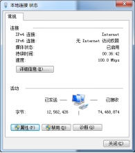
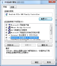
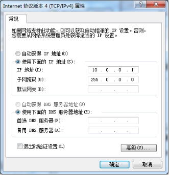
The correct computer IP must be set before running the software , otherwise the software cannot run normally.
Click on the status bar in the network connection icon to select local connection for local open Network and Sharing Center IP settings. The IP is set to10.0.0.1 , and the subnet mask is set to: 255.0.0.0 .![]()
① |
② |
③ | |
Double-click the installer software.
Click , it will appear after the software is started
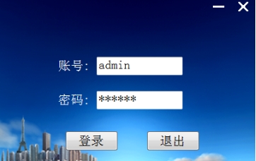
Default username : admin , default password : 123456
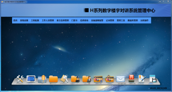
After logging in, enter the management center interface
System settings
Community information settings
Set the community name and upload the community map .
The system defaults to no area.
If the size of the community is large, it can be set to have multiple districts, and the operation according to the district is convenient for the owner's information management, card management, information release, etc.
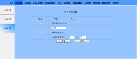
When the system is turned on, the time interval can be set.
Networked devices include management machines, wall machines, and networked swiping heads .
Select the project configuration, select the networked device configuration, enter the read networked device, enter the actual building number ( 1-99 ), unit number ( 1-9 ), click , and the search will automatically generate a list of all networked devices . When there is no unit number, the default unit number is 1 .
The system supports the configuration of 1-32 management machines .
The system supports the configuration of 1-32 wall machines .
Configuration
The system supports 10 sets of networked credit card head of the configuration .
Supports 0 - 99 buildings, a complete circuit 0 - . 9 arranged units.
Each unit can be added . 1 - 10 sets of door machine
Each unit supports up . 6 . 3 layers, each supports up to 32 users.

◎ Click to view indoor unit to view the list of indoor units of this unit .
◎ Click the single add indoor unit , you can enter the household number ( 3 digits / 4 digits ) to add a single indoor unit .
◎ Click the matrix to add the indoor unit , you can enter the starting household number and the ending household number, and click to add the indoor unit to the matrix . 
◎ Click Copy indoor unit to enter the copy unit interface , and copy the indoor unit configuration of the current unit to other units .
In the cell structure settings of the system settings , you can turn on this setting item after setting it to have a district.
Supports adding regions and assigning units to each region.
The software supports the management of machine , wall unit , the first network card, door phone , credit card head unit, indoor unit , single-family door phone and lift linkage module of Ping detection and version View.
Select the corresponding device type and enter the device number, click Ping to detect, the host computer will return whether the Ping of the device is successful.
Support manual time adjustment function, click to synchronize the time of other devices in the system .
This software supports the detection of the IP addresses and MAC addresses of digital devices in the entire network . If there are the same IP addresses, the list will display : IP conflicts.
Enter the correct administrator password and click .
This software supports the entry and management of staff information, including department management, staff addition and viewing staff lists, etc.
Add or modify the department where the staff is located. After adding, in the staff adding interface, the staff's department can be selected.
The staff information can be entered, including basic staff information, contact information, department and position. In addition, management authority can be assigned to staff. The staff can log in to the software with the account and password set here to perform operations and settings within the authority.
The personnel list can be viewed or modified. The list contains account number, name, gender, date of birth, department and position information.
Input operation according to the owner's information.
List
Display owner information in a list.
Supports single, batch registration, list viewing of access control cards , and reading the registered access control card data from the card reader into the software.
Single card registration

Access card entry methods include: manual entry of the card number or card issuer swiping entry (need to select the computer COM port connected to the card reader ) .
Bulk card registration

◎ Import from the database:
When replacing the device, the card information that has been stored on the host computer can be re-imported into the door phone, wall phone or indoor phone.
◎ Import from file:
Support .txt/ .xls file import.
The access control card list can be searched, viewed or modified. The list contains card number, card ownership, card status and operation information.
The registered access card data can be read into the software from the card reader of each device. When reading, the card type, device type and device number can be selected for reading.
Support the release of indoor unit announcements, indoor unit private information, door phone announcements, and support for receiving and querying information sent from indoor units .

Announce the indoor unit announcement , you can choose the receiver as a single or broadcast to all units .
Only one household can be selected to publish private information of indoor unit .
Door phone announcement: You can choose to receive a single or all door phones, and broadcast to all means to broadcast to all door phones and wall phones in the community .
Disconnection alarm: When a device in the system is disassembled or power failure occurs, the administrator can choose whether to detect the fault through the upper computer and report the fault information.
manage
Information management includes the functions of querying, viewing, exporting and deleting alarms , arming and disarming, unlocking, call and message sending records.
With data backup and recovery functions.
Support remote upgrade of management machine, wall machine, door machine, indoor machine and single-house door machine .
It can remotely push pictures to indoor units , door phones, wall units, and management units . The size of the pictures pushed by each device is as follows:
Location | name | size | Size ( byte) | Format (24-bit) |
System settings | map | 600*431 | Less than64K | *.bmp |
Owner information list | Household photos | Unrestricted | Less than64K | *.bmp |
Staff list | Staff photo | Unrestricted | Less than64K | *.bmp |
Information Release | Information Picture | 200*150 | Less than200K | *.bmp |
LOGO push | Indoor unitLOGO | 252*153 | Less than200K | *.bmp |
Management machine LOGO | 800*100 | Less than200K | *.bmp | |
Door phone LOGO | 272*160 | Less than200K | *.bmp | |
Background push | Indoor unit background | 800*480 | Less than1.1M | *.bmp |
Management machine background | 800*480 | Less than1.1M | *.bmp |
9. Other matters
Power configuration requirements : indoor extensions and door phones can use PoE power supply or independent power supply. The power distribution of the system must meet the requirements of system operation and have a certain margin. The power distribution system must ensure reliable, safe, and reasonable power supply and distribution to the system.
Line requirements: The backbone of the residential area can be connected by optical fiber or Cat 5e network cable according to the actual situation of the project, and Cat 5e cable is used for all units to the home.
Equipment part: One , two, and three switches can be set according to the site conditions. The switches must comply with IEEE802.3 , IEEE802.3u , IEEE802.3ab , and IEEE802.3x standards; support 10/100/1000M adaptive Ethernet ports ;
Indoor wiring: The wire used for the digital video intercom is a Category 5e unshielded network cable. If it is not more than 90 meters in the multi-layer and small high-rise wiring, it can be directly laid in the first-layer integrated cloth box. When laying the cable, be sure to pay attention to civilized construction And make a mark;
High-rise wiring: Regardless of whether there is an effective value exceeding 90 meters in high-rise wiring, the hierarchical management of switches needs to be considered when designing;
Reserved indoor bottom case: video intercom indoor unit reserved for the bottom box 86 bottom box, around the end of the cartridge 20 can not have an inner cartridge bottom designing other cm;
Location of door phone and single-family door phone: The design camera height of the door host is 1.6 meters. At the same time, attention should be paid to the cooperation with the access control, door lock and lock control parts, and direct sunlight and heat dissipation issues should be considered;
Outdoor pipeline design: The design of outdoor pipeline must first determine the size of the pipe diameter according to the number of wires. The pipeline must reserve 40% of the space. Pay attention to the problem of cross-operation with other types of work and common routes and common routes in the weak current industry (such as: pipeline laying has problems, alignment problems and the pipe shaft provided in the holes), weak strong electric conduit pipe holding some50 cm distance laid in parallel, intersecting the same time holding down distance 50 above centimeters;
Design of outdoor optical fiber: According to the erection needs of the site engineering, if the communication distance from the unit to the computer room is relatively long, the optical transceiver can be used for signal conversion and long-distance communication to the computer room networking;
The design of the integrated wiring box : The integrated wiring box must be well protected against lightning, strong current surges, heat dissipation, leakage protection, lightning protection sockets and equipotential grounding.
Switch : The switch used in the system network connection can be set up with a layer 2 switch. If there is a special need to use a layer 3 switch, the configuration of the layer 3 switch needs to be done;
In order to ensure the normal operation of the digital video intercom system network of Shenzhen Zhensheng Intelligent Electronics Co., Ltd. , the following suggestions are made for network construction:
1 , using the hierarchical network design, network management easy to optimize network performance, enhanced network scalability ;
2 , the cell must be greater than the bandwidth of the backbone network 100Mbps , tenants speed network access port at least 10Mbps which requires network100M to the floor , 10M / 100M home;
3. The IP address of the network equipment must be allocated reasonably in the local area network of the community to ensure that the network IP address of thevideo intercom equipment does not conflict.
In order to ensure that the intelligent visual intercom system of Shenzhen Zhensheng Intelligent Electronics Co., Ltd. can work normally, the network system must be able to operate safely and reliably around the clock;
Our company attaches great importance to technical support and after-sales service, because we know that the competition in the market today has changed from the past product competition to the service competition. It is precisely because the company fully recognizes the importance of service to users, so our company has established a complete system and strict management after-sales service organization within the company, and has an experienced, sophisticated technology, and wide-ranging technical support and after-sales service. Service expert team. Its main manifestations are as follows:
Rigorous and standardized management system
Our company has a very rigorous and scientific after-sales service and technical support management system. There are unique technical measures and strict rules and regulations. The engineering and technical personnel of our company have received formal technical training from the cooperating manufacturers with our company and the country, so there is a well-trained technical support team. It can solve the technical problems that arise in the process of use for customers at any time, and the level and quality of its services have reached the standards specified by the company and the indicators specified by the suppliers.
Terms of Service
Based on the above conditions, our company solemnly promises users the following service content:
( 1 ) Warranty period
In order to create the best and safest use environment for users, our company undertakes the technical support and service of the entire project integrated wiring and intelligent system. In addition to human factors (such as equipment damage bad ) , outside rodents and force majeure (such as earthquakes, floods), all equipment provided by the company sells 15 Warranty months, during the warranty period, repair or replace all equipment are It's free.
( 2 ) Special technical services and support methods
After the warranty period, we will provide a preferential contract warranty, replace damaged parts and spare parts at the cost of the price, and provide free technical consulting services during the warranty period to answer difficult questions for users.
( 3 ) Response time of hotline service / field service
The response time of our company's hotline service is within 2 hours, that is, after receiving the user's request notification, the service plan and action arrangement will be notified to the customer within 2 hours by phone or fax .
( 4 ) All expenses incurred during the on-site warranty period, including personnel transportation, travel services, etc., shall be borne by the company.(Except for system damage caused by abnormal accidents) .
( 5 ) After each service is completed, the company will submit a formal after-sales service report to the user, which shall be signed and approved by the user.These reports will serve as my company's technical file for safekeeping, so that in the future to better serve users .
( 6 ) For services outside the warranty period, the company still guarantees to provide users with services of the same quality during the warranty period, including service response time, arrival time, and the effect of solving problems.
( 7 ) Our company will provide long-term support and service for the integrated wiring and computer network system used in this project, and timely update and upgrade for users, and only charge the cost.
Appendix:
1. Manual of Management Center
2. Manual of door phone
3. Manual for indoor unit
4. User manual of single household door phone
5 , PC management instruction manual
Sweep and pay attention to us